Custom Carbon Fiber Motorcycle Body-kit
In the Spring of 2016 I worked under MIT's Electric Vehicle Team to modify an electric motorcycle by reducing mass and aerodynamic drag and optimize drive strategy for the Pikes Peak Hill Climb, the 4th oldest motorsport event in the Western Hemisphere. I was the lead aerodynamic designer and fabricator for this project. Throughout a semester we were able to design, simulate, and build a custom carbon fiber motorcycle body-kit.
PRELIMINARY Research
Electric motorcycles are limited by the power density of the batteries. This restricts them from competing in long races. In order to have the fastest motorcycle, it is necessary to utilize every joule of energy. This means reducing the waste of energy in order to utilize that energy for the motor. One of the largest inefficiencies is due to aerodynamic drag. Drag force is proportional to the frontal area of the vehicle. The effect of velocity on drag follows a square law. The effect of velocity on the power requirement is proportional to the third power of the air speed. Delayed detached-eddy simulations show that the average coefficient of drag for a super-sportive motorcycle is 0.45 - 0.60.
Initial Design
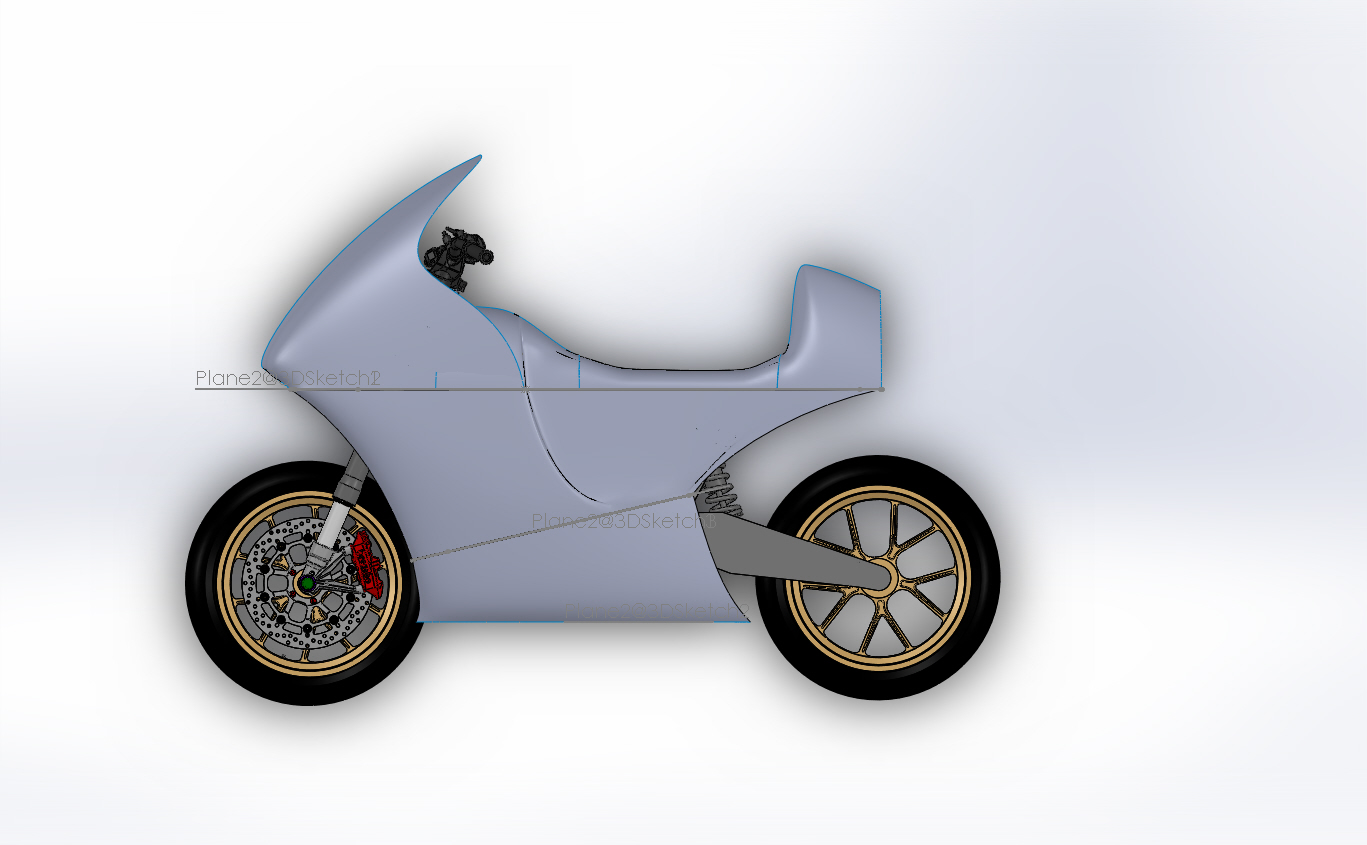
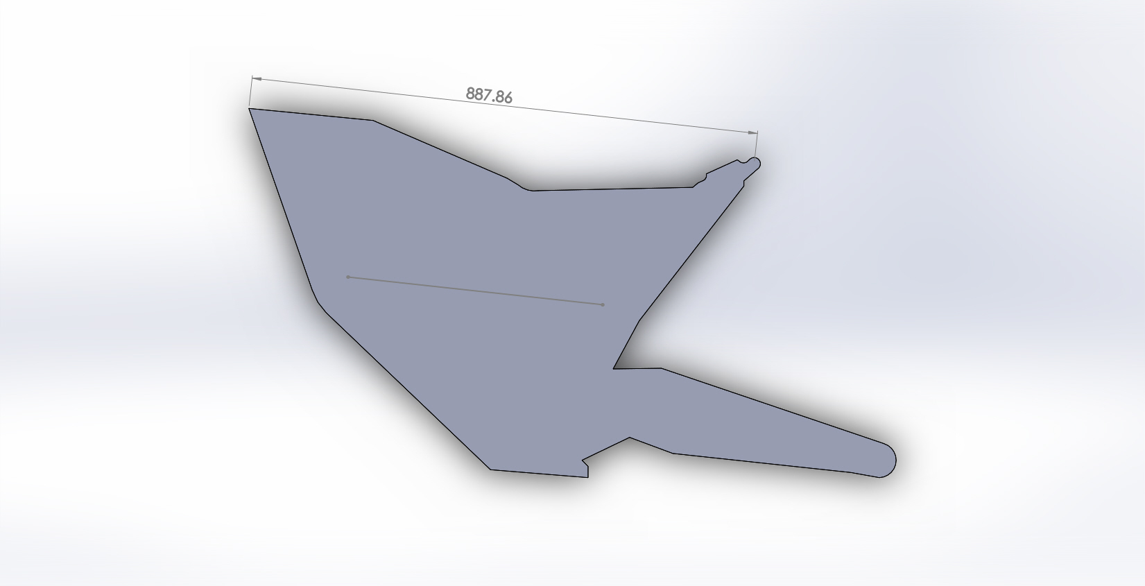
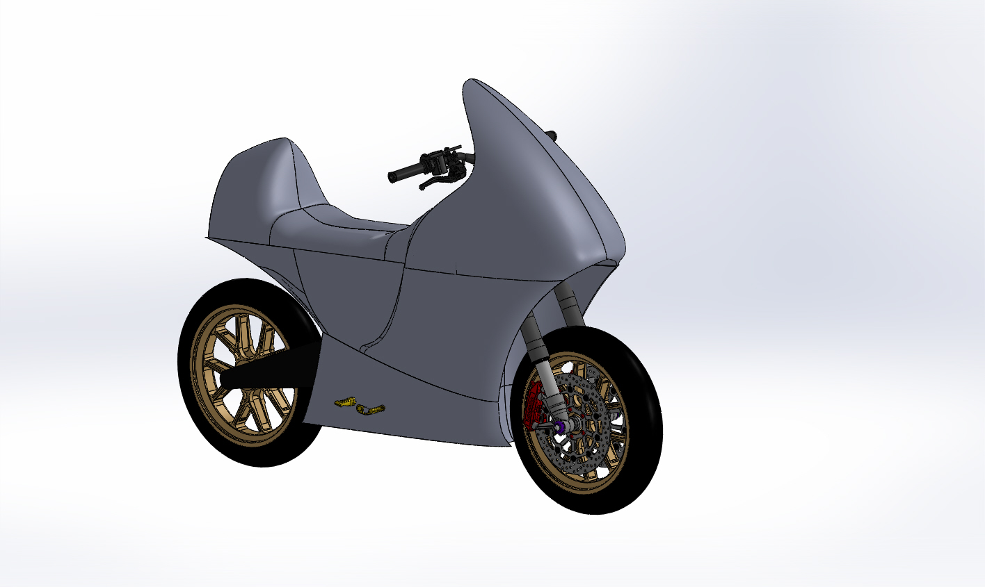
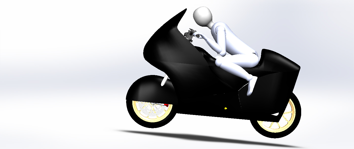
Due to the lack of open source fairing CAD and the particular shape of our bike, we decided to create our design from scratch. The fairings have since been custom fit to the rider and his optimal race position. In addition, with foresight of fabrication and attachment, we separated the body in key positions. The final design divided the body contour into 6 different segments, based on ease of assembly, durability in mounting, and necessary practical considerations including battery removal and charging.
Simulation
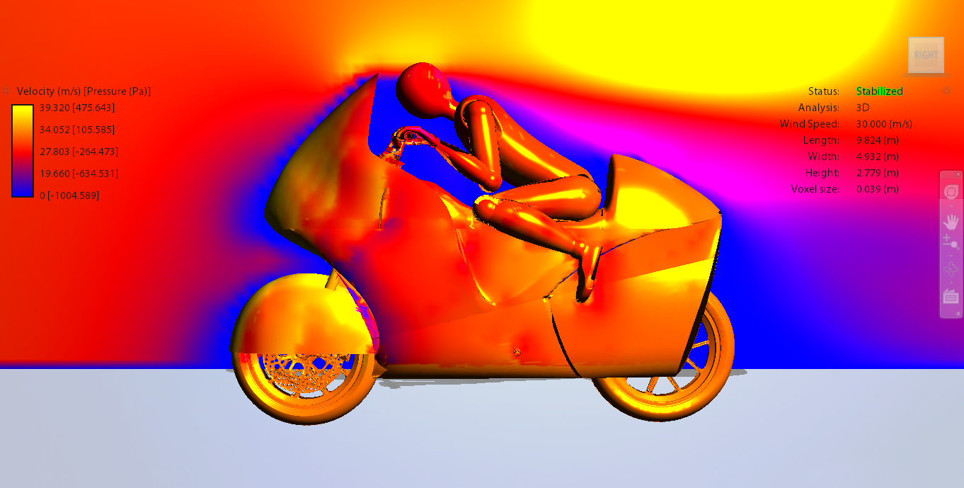
In order to refine our design, we used Autodesk wind tunnel simulation. While this is not a high end flow simulation, we were able to smooth out the high pressure zones and see the simple air flow. One flaw of this simulation is that the vehicle is static while the air is moving. The relative speed of the motorcycle to the air is correct but the simulation does not take into account the effect of drag from the front wheel. Since the top of the front wheel goes against the wind, it contributes much greater toward drag than the models show. Lastly, we ensured that the side forces are mitigated through the bike.
Fabrication: Mold
Molds can be created out of different material, but we chose to use 2 inch insulation foam due it being cost effective, easily obtainable, and can be easily cut. After firmly securing the foam to the table, we decided to cut each part in 2 inch layers in x and y, 3D raster. This allows to have more pronounced curves than a simple 2D cut and by doing both the x and y rasters, the grid over the piece reduces the step size in both the horizontal and vertical direction. Once each layer is created, they must be glued together and sanded down. In order to smooth out the mold more and fill in gaps between layers, we covered the mold with epoxy with microbeads. The microbeads allows the mixture to have paste consistency which allows it to be easily spread, no drip, and fill in gaps. After curing, the microbeads creates a nice surface for sanding down. This process can be done multiple times to get the quality that is necessary for your application. Microbeads also help to make the molds reusable to make multiple parts with the same mold.
Fabrication: laying up the material
The second step, laying up the material, requires mostly prep work. Prepping the mold requires a two step process. First applying 2 coats of wax with an hour to dry in between, followed by 2 to 3 layers of polyvinyl alcohol and polished to a hard gloss allowing 10- 15 minutes to dry in between. These two combined create excellent release characteristics which reduces the time taking the part off the mold from hours to minutes and allows the mold to be reused for multiple parts.
In order to lay up a mold, you will need the following sheets of material: fiberglass or carbon fiber with the number of layers for your application, bleeder/ breather cloth, peel ply, and vacuum bagging. The material must then be cut to fit over the whole portion that you want as your part. Doing composite work is a relatively simple process but contains a bunch of small tricks in order to get a professional finish. The main steps are: spreading epoxy over the full sheet of material; laying the material over the prepared mold, spreading it into the curves of the mold; covering the whole thing with peel-ply, bleeder cloth, and vacuum bag in that order; securing a tight seal around the part between the vacuum bag and table, and vacuuming the part to create constant pressure on the whole thing.
Each step in laying up material has small nuances that must be done in order to have a professional part and stay safe. For non-flat surfaces, the material will have to be spread which will require a larger sheet than measured. Cut the bleeder cloth larger than the sheets of material to ensure that it can absorb any extra epoxy, but cut the peel-ply even larger, to ensure that the bleeder cloth does not directly touch the material or the two will stick together. Ensure that the vacuum bag can cover the whole part and seal on all sides around to the table with enough room for play as it will have to pull into the whole mold. Get 2-1 epoxy to hardener mix, because it will give you enough time, around 30 minutes, to work with the epoxy before it starts to cure. Do not work in a relatively cold room, or the piece will take longer than the 8 hours to cure.
Fabrication: Finishing
The last process is finishing. This involves cutting the extra material with an oscillating saw, sanding down the material starting with 80 grit to get rid of the ripples caused by folding material, followed by 400 grit to get a smooth finish. Afterward, the part is ready for painting. In order to get a high gloss paint, you need to apply a few layers of color and let it dry. After drying, it will have orange peel. Apply a few coats of clear on top. The orange peel will come to the surface and can be sanded and buffed down after to allow a high gloss surface. Proper painting techniques in a ventilated room are necessary to get a pro-finish.
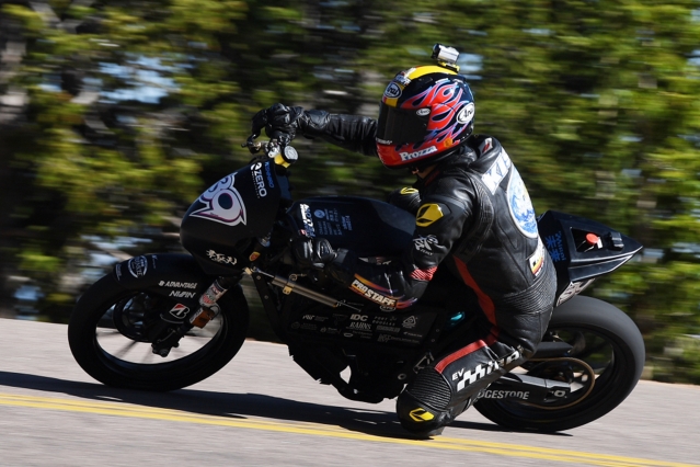
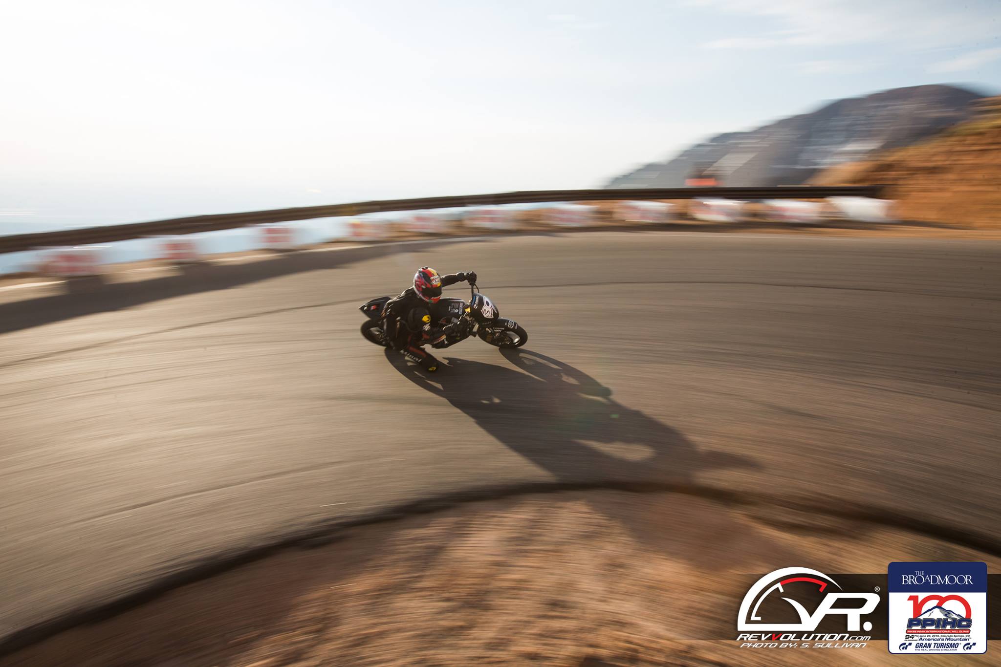
Race Results
We placed 2nd in the Electric Bike category with a time of 11:10.480. Pikes Peak International Hill Climb wrote an article on our project, ACADEMICS & MOTORSPORT COMBINE AS THE MASSACHUSETTS INSTITUTE OF TECHNOLOGY & INTERNATIONAL PARTNERS ENTER AN ELECTRIC MOTORCYCLE IN THE BROADMOOR PIKES PEAK INTERNATIONAL HILL CLIMB. And MIT News published the following: Team led by MIT engineers places second at Pikes Peak International Hill Climb.